


CNC Series JMNC53+NP50+D53
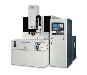
Developed by a group of top engineers and technicians with rich on ground and theoretical experience in the field of EDM, JMNC53+NP50+D53 renders superb engineering supremacy and unmatched mechanical features to outstand others.
- Specs
- Accessories
- Features
- Controls
- Cut Samples
- Video
- Inquiry
MACHINE UNIT & DIELETRIC TANK UNIT
| ITEM | UNIT | JMNC53+NP50+D53 |
|---|---|---|
| Work table size | mm | 800 × 550 |
| X travel | mm | 500 |
| Y travel | mm | 350 |
| Z travel | mm | 350 |
| Ram platen to work table | mm | 310 ~ 660 |
| Max. electrode weight | kgs | 150 |
| Max. workpiece weight | kgs | 1600 |
| Work tank ( W × D × H) | mm | 1160 × 670 × 340 |
| Weight of machine unit | kgs | 2800 |
| Machine Outside dimensions ( W × D × H ) | mm | 1430 × 2175 × 2330 |
| Max. Machining Current | A | 50 |
| Total Power Input | KVA | 4.5 / 6.5 ( with JMNC53P ) |
| Max. Metal Removal Rate | mm3 / min | 390 |
| Electrode Wear Ratio | % | 0.20 |
| Best Surface Roughness | µm Ra | 0.20 ( without powder ) < 0.20 ( without powder ) |
| Net Weight | kgs | 320 |
| Outside Dimensions ( W × D × H ) | mm | 680 × 1070 × 1820 |
| Dielectric tank capacity | L | 600 |
| Dielectric tank pump | HP | 0.85 HP × 1 |
| Dielectric tank net weight | kgs | 180 |
| Dielectric tank filter method | Paper filter | |
| Dielectric tank outside dimensions ( W × D × H ) | mm | 2060 × 800 × 1160 |
* All specification and design are subject to change without notices.
STANDARD ACCESSORIES
| Paper filters 1 set |
| Tool box 1 pc |
| Flushing nozzle 1 set |
| Drill chuck 1 pc |
| Clamping kit 1 set |
| Electrode holder 1 pc |
| Halogen machine work lamp 1 pc |
| Leveling pads 1 set |
OPTIONAL ACCESSORIES
| Auto fire extinguisher |
| Permanent magnetic table |
| Dielectric cooler |
| Auto Electrode Changer ( For CNC EDM only ) |
| 3 or 4 Tools for JMNC32A & JMNC43A |
| 5 Tools for JMNC50 & JMNC53 / JMNC53P |
| 6 Tools for JMNC60 ~ JMNC2210S |
| C-axis ( For CNC EDM only ) |
| Spare PCB set |
FEATURES

| Industrial grade PC based CNC controller |
| 12.1” TFT LCD color panel |
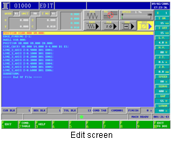
| Dialogue programming or GM code programming |
| Background editing |
| User Macro function |
| Multi language support |
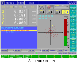
| Machining path display |
| MPG positioning and discharging alignment |
| Multi-holes macro programming: Linear / Circular / Array / Arbitrary Multi-holes |
| Multi-conditions macro programming for finish machining |
| 1000 machining condition tables with 1000 conditions in each table |
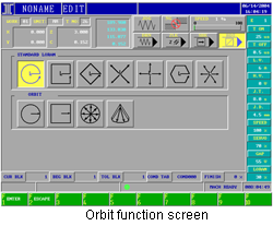
| 17 kinds of Loran & Orbit function |
| LWF sparking circuit able to control the peak current rising slope, reduce the corner wear |
| Tracking mode OFF-TIME control circuit to prevent Arcing |
| All PC boards are sectioned in modular box design, reduce maintenance cost |
SOFTWARE SPECIFICATION :
| Language : English / Chinese |
| Unit Inch : system / Metric system |
| Programming : Dialog programming / G/M code programming / background programming / expert system auto-programming / RS232/ Network |
| Operation : mode Auto / Manual / Edit / Manual Data Input ( MDI ) |
| Screen function : Expert / Graph / Diagnostic / Alarm / Set |
| Software panel function : DRN / SBK / BDT / ZLK |
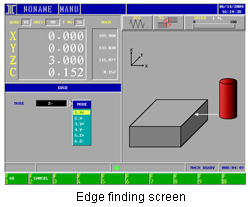
| Positioning function : Rim Searching / Groove Center Searching / Hole Center Searching / Outer Center Searching / Apex / Sparkle Tooling Correction |
| Machining function : Orbit Cutting / Cone / Planar Expansion Orbit / Vector Orbit / 3-Dimension Orbit / Machining Along Path / Time Limited Machining / Multi-Hole Macro / Multi-section Finishing / Cutting with C Axis |
| Offset function : Tool Length / Tool Radius / Gap / Thread |
| MLC function : I/O Point / C Point / S Point / A Point / Timer / Counter / Temporary Saver / D Temporary Saver / Real-Time Ladder Diagram Display |
| General function : Multi-Coordinate System / Coordinate System Zoom Scale / Coordinate System Rotation / Graph Rotation / Machining Path Display / User Macro Command / On-Line Instruction |
| E code number : 1000 |
AXIS CONTROL :
| Basic axis : 3 Axis |
| Extended axis : 1 ( C axis, optional ) |
| Numbers Of Basic Co-axis : 3 Axis |
| Number Of Simultaneously Driving Axis : At most 4 Axis |
| Number Of Hand Wheel's Controllable Axis : 3 Axis ( Optional for C Axis ) |
SYSTEM SETTING UNIT:
| Metric - Minimum Input Unit : 0.001 mm / Minimum Command Value : 0.001 mm / Maximum Stroke Setting : 9999.999 mm |
| English - Minimum Input Unit : 0.0001 inch / Minimum Command Value : 0.0001 inch / Maximum Stroke Setting : 999.9999 inch |
| Angle - Minimum Input Unit : 0.001° / Minimum Command Value : 0.001° / Maximum Stroke Setting : 359.999° |
G CODE TABLE :
| Positioning Function - Function : Rapid Positioning / No-Guard Rapid Positioning / Edge Finding / Groove Center Finding / Hole Center Finding / Outer Center Finding / Apex Finding / Home Origin Finding / Sparkle Tooling Correction / Automatic return to Reference Point / 2nd Reference Point Return |
| General Machining - Function : 3 Axis Linear Cutting / Clockwise Circular Arc Cutting / Counter-Clockwise Circular Arc Cutting |
| Orbit Macro Machining - Function : Circular Macro / Square Macro / Vector Macro / Fan-Shaped Macro |
| Loran Machining - Function : Standard Loran Machining / Loran Pattern Rotation / Plane Setting of Expansion Loran / Angular Loran |
| Multi-hole Macro Machining - Function : Linear / Circular / Arc / Square / Random Mode of Multi-hole Machining |
| Time Limited Machining - Function : Cutting Time Setting For Time Limited Machining |
| Macro - Function : Call Macro Command |
| Coordinate System Function - Function : Machine Coordinate System / Working Coordinate Systems / Polar Coordinate System Command / Zoom Scale / Coordinate System Rotation / Absolute/Incremental setting / Setting Coordinates of Current Position / Selection of Working Plane / English / Metric Conversion |
| Compensate Function - Function : Tool Radius Compensation / Tool Length Compensation |
| C Axis Function - Function : C Axis Home Origin Finding / C Axis Helical Machining / Helical Positioning / C Axis No-Guard Helical Positioning |
| Other - Function : Dwell / Data Setting / Stored Stroke Check Function |
| Pumping Mode - Function : Pumping Along Current Machining Axis / Pumping Upward Along Z Axis / Pumping Along Machining Path / Pumping to the center and then Along Current Machining Axis / 45°back to the Center and then Along Current Machining Axis |